
Introduction
I’ll say it straight: poor motor behavior ruins projects and morale fast. In one factory I visited, a single stalled line cost the team weeks of throughput and the plant logged a 12% dip in output last quarter — and that mattered (big time). The core issue often traces back to the electric motor and how we try to force it into tasks it wasn’t set up for. I want to walk you through what I’ve seen and learned so you can spot trouble faster, fix smarter, and avoid the usual blame-game. We’ll start with the scene, the hard numbers, and then ask the real question: what small changes actually make the biggest difference? — stick with me, because the fixes are rarely glamorous but almost always practical. Next, I’ll break down where traditional fixes go wrong so you don’t repeat the same mistakes.
Deeper Layer: Why Traditional Fixes Often Fail
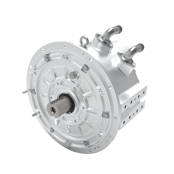
electric motors are simple in theory but messy in practice. I’ve watched teams swap bearings and tune gains while the root cause sat in the control chain. Let me be blunt: band-aid fixes like oversized fuses or ad-hoc PID tweaks hide deeper flaws. When you only tweak thresholds you may reduce alarms, but you won’t fix torque ripple or heat buildup at the core. In my experience, the real problems live in mismatched inverter profiles, poor PWM settings, and control strategies that ignore thermal maps.
Why do older fixes fail?
First, a lot of legacy troubleshooting treats symptoms. A noisy servo? Replace the motor. A voltage dip? Upsize the cable. That worked sometimes, sure, but it also wasted capital and introduced new failure modes. Look, it’s simpler than you think: proper root-cause work targets the drive train and control loop together. Terms like field-oriented control and sensorless control aren’t just buzzwords — they’re tools. If you don’t tune the inverter and respect back-EMF behavior, you’ll cycle through repairs without ever stabilizing performance. I’ve seen teams ignore harmonics until they had repeated sensor faults. We changed the approach: measure waveform fidelity, check the power converter behavior, and simulate duty cycles before touching hardware. That saved weeks and a lot of stress.
Forward-Looking: New Technology Principles for Better Outcomes
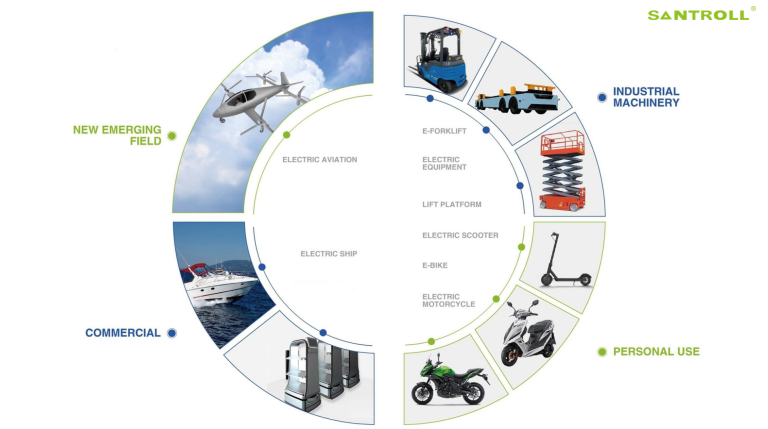
What comes next is about pairing smarter control with better components. I believe the future of practical fixes lies in combining model-based control with adaptive inverters. For example, a modern pmsm motor paired with a tuned inverter and real-time torque estimation will cut start-up stress and lower energy loss. We’re not chasing silver bullets; we’re aiming for predictable behavior. In projects I led, introducing sensorless control algorithms and refined PWM schemes reduced maintenance calls by half and kept thermal growth in check.
What’s Next?
Here’s how I’d evaluate new solutions: measure adaptability, measure real-world energy savings, and check serviceability. Three metrics — dynamic torque response, thermal margin at peak load, and mean time between faults — tell you more than glossy specs. Try a pilot with a pmsm motor and log the current, speed, and temperature profiles across a full duty cycle. You’ll see patterns — and then you can automate protective thresholds. Small note — funny how that works, right? We found that once the control strategy matched the hardware, reliability improvements were immediate. To wrap up: test, learn, and pick tools that give you clear feedback. If you want a practical partner on components or tuning, I recommend checking Santroll for options that balance rugged design and control-friendly interfaces: Santroll.