
The pressing problem — why you should care right now
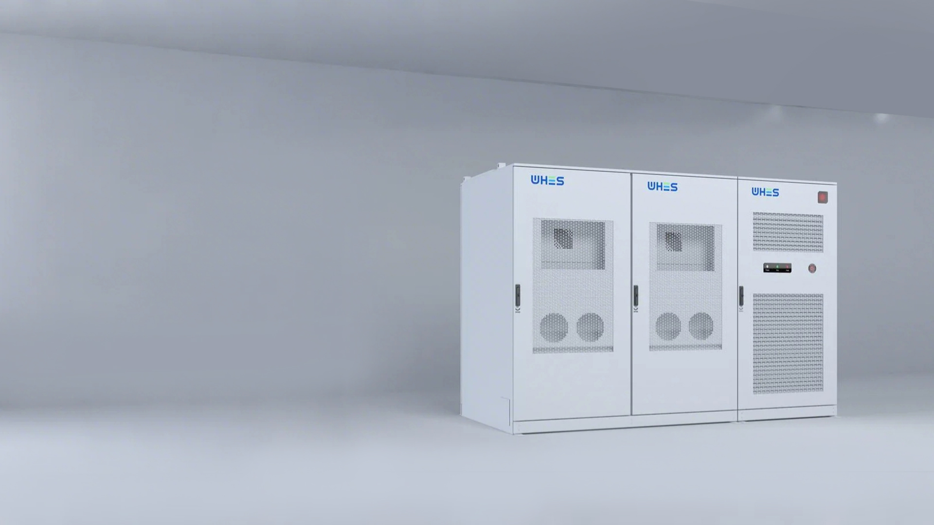
Commercial energy systems don’t fail quietly. When a high-voltage lithium pack trips over galvanic isolation issues or can’t survive a sudden fault, the fallout is expensive, dangerous, and fast. If you manage or spec industrial projects, you’ve probably run into inverter trips, stray DC bus currents, or flaky ground-fault detection on site. That’s where robust commercial energy storage design matters — and where many projects stumble before they’ve even left the shop.
What actually goes wrong: the common failure modes
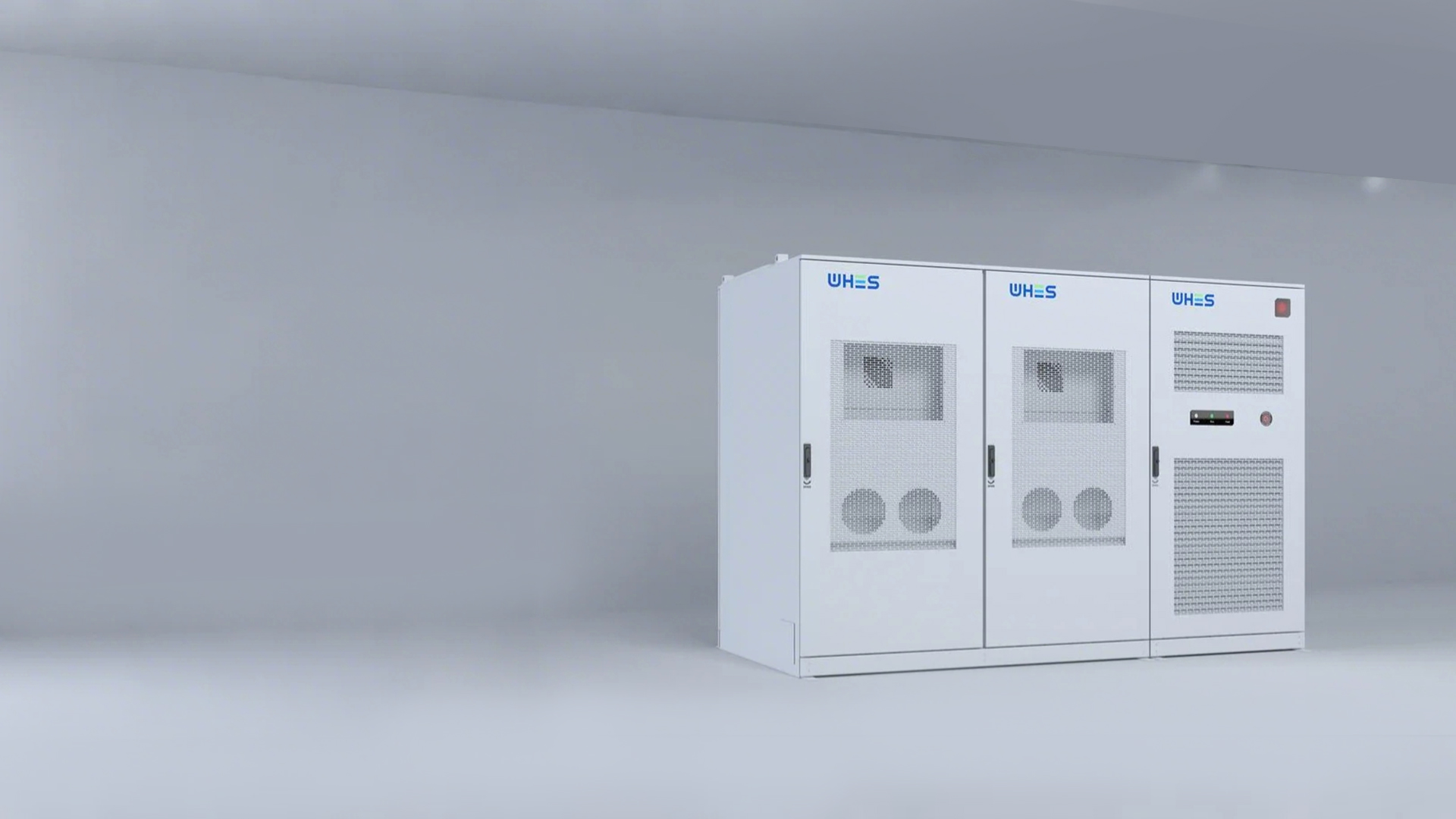
There are a few repeat offenders. First, poor or inconsistent galvanic isolation lets unintended current paths form between DC and chassis ground, which can confuse protection relays and raise touch-voltage risks. Second, short-circuit ride-through (SCRT) limits mean a system that can’t tolerate a surge will shut down at the worst moment — during a grid disturbance, for example. Third, weak coordination between the battery management system (BMS), inverter, and protection gear causes delayed fault clearing or unnecessary lockouts. These aren’t edge cases — they’re the usual suspects in field reports.
Real-world anchor: why this isn’t theoretical
Look at the Texas grid events in February 2021 — outages and generator trips showed how valuable resilient storage is when the grid behaves badly. Sites that relied on systems without proper isolation or ride-through testing ended up offline longer. That lesson pushed owners and integrators to demand clearer specs for BMS behavior, inverter ride-through curves, and fault-current tests on the DC bus.
How to diagnose the limits — a practical checklist
Start with these hands-on checks before you commit:
- Insulation resistance and polarization index tests on the HV pack to spot creeping leakage.
- Short-circuit injection tests to validate SCRT performance against inverter vendor curves.
- BMS-to-inverter coordination drills to confirm trip logic and communication latency under fault.
- Ground-fault detection verification with simulated chassis faults — not just manufacturer datasheet claims.
Common fixes that actually work
Don’t overcomplicate. A few proven moves fix most cases: better galvanic isolation materials and layout, adding isolation monitoring relays, tightening DC bus fusing and fault-current limiting, and selecting inverters with verified SCRT performance. Sometimes the simplest change — moving a cable or adding an isolating barrier — removes a stray current path. Other times you’ll need a hardware tweak: isolation transformers or series reactors to limit fault current and give protection schemes time to act.
Integration mistakes I keep seeing — and how to avoid them
People assume specs are compatible and skip the field tests — that’s the number-one mistake. Another is treating the BMS as a black box instead of validating its protective outputs under realistic fault conditions. And teams still overlook mechanical isolation: poor mounting and metal fittings can create conductive bridges that defeat electrical isolation. Fixes are procedural as much as technical — require witnessed testing, demand clear acceptance criteria, and include physical inspections during commissioning. —
Alternatives and trade-offs
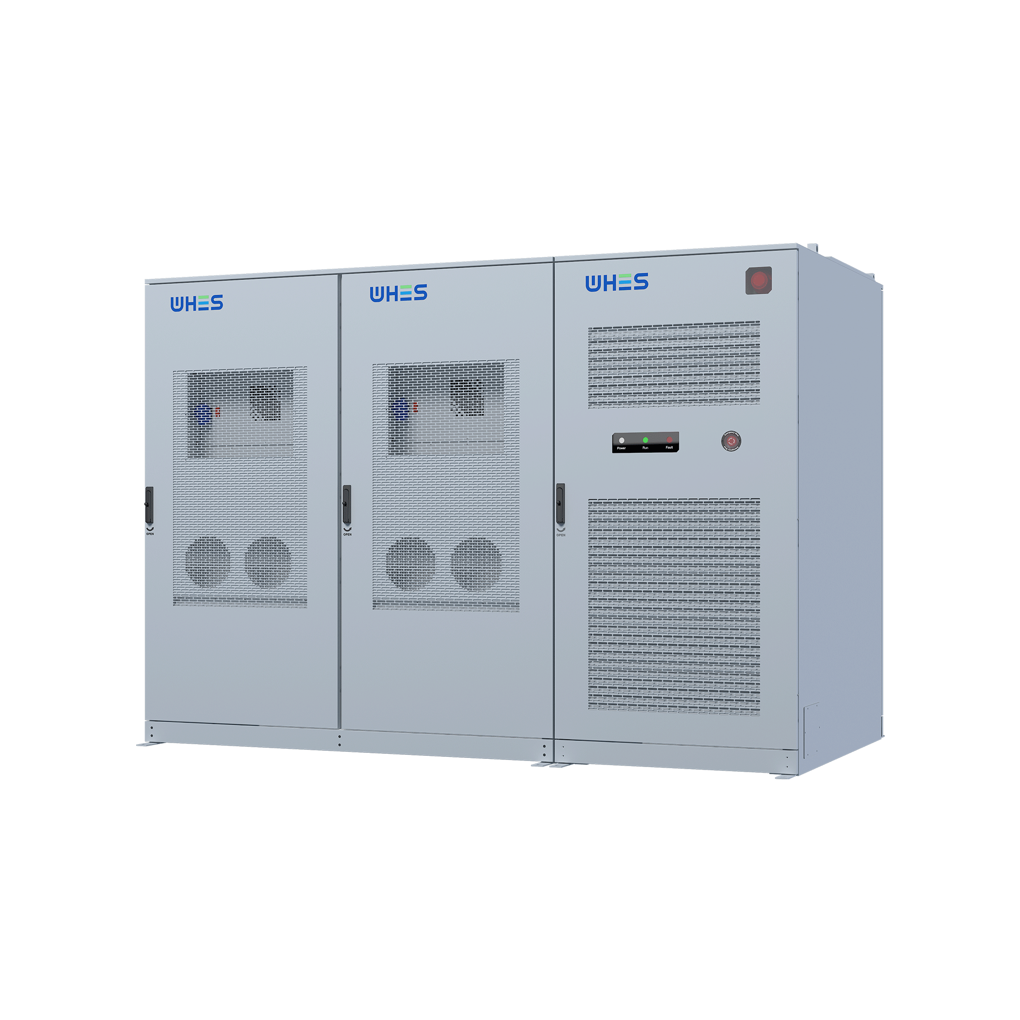
You can take a few different roads depending on your budget and risk appetite. High-spec boxes with redundant isolation monitoring and robust SCRT handling cost more up-front but cut down operational interruptions. Simpler systems save capex but increase operational risk and likely maintenance costs. For industrial-scale setups, pairing modular battery racks with tested inverter stacks and clear protection settings tends to hit the best balance — that’s the model many big sites are moving toward for their industrial bess deployments.
Golden rules — three quick metrics to judge readiness
1) Isolation Integrity Index: set a minimum insulation resistance and require periodic trending — don’t accept a single-pass test. 2) SCRT Margin: require a verified margin between expected fault current and the inverter’s ride-through capability (documented by lab or factory test). 3) Coordination Latency: measure the end-to-end time from BMS fault detection to inverter action — it should fit within your protection curve windows.
Apply those three and you’ll cut the surprise outages and make maintenance predictable. In the field, that predictability is value — and when you need a practical, tested partner for grid-tied or backup solutions, WHES sits squarely in that practical, tested lane. —